C = Coil (connect to coil negative side)
EXT = connect into negative post of power supply
B = connect to positive post of power supply
T = connect to red wire from function generator
FIRST IGNITION CIRCUIT

i then had to draw the circuit diagram:

as you can see there is a 12 volt battery supply, this goes into the primary side of the windings in the coil and charges up the secondary windings.
this then comes out of the other primary side of the coil and into the ignition module.
the function generator then sends a pulse to the ignition module which grounds the circuit.
the secondary windings are also grounded and are able to spark the spark plug.
SECOND IGNITION CIRCUIT

i then had to draw this diagram :
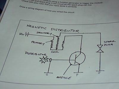
in the diagram above the 12 volt battery supply goes into the primary side of the coil and charges up the secondary.
the other side of the primary windings goes down into the ignition module and as the distributor spins around, the ignition module grounds the circuit and the secondary winding releases its spark and sparks the plug.
THIRD IGNITION CIRCUIT

I then drew circuit diagram of the above circuit:

i the above diagram, the 12 volt battery supply goes strait to the firing spark plugs but can only fire when the function generator sends a pulse to the igniter and grounds the circuit. this will then allow both spark plug to fire.
FOURTH IGNITION CIRCUIT

i then was asked to draw a diagram of the circuit:

in the above diagram, the 12 volt battery goes to the primary side of the coil which charges up the secondary windings. this will not spark until the function generator grounds it and sends a pulse.
No comments:
Post a Comment