Engine Coolant Temperature Sensor
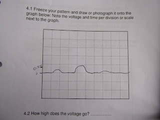
i hooked the engine up to an oscilloscope and then let it idle while is was cold and kept reading the oscilloscope while it was heating up
in the above oscilloscope reading, you can see as the line is at the higher point it is cold and when the engine starts warming up the line starts going down, this means the voltage is dropping.
this reading could be faulty if the sensor had a bad earth or a faulty thermistor this could cause the engine to over heat.
MAP Sensor
For this sensor i hooked up the oscilloscope up to the output wire and to the ground wire i then gave then engine a few quick revs
when i snapped the accelerator i found that the voltage went up because there was no vacuum and when i had the engine at idle there was not much voltage because there was full vacuum.
is the sensor was giving a faulty reading it could be because there is a bad earth or the vacuum line is not on properly or leaking.
if the hose was leaking or not attached the sensor would be reading no vacuum so it would tell the ecu to squirt maximum fuel into the combustion chamber.
Throttle Position Sensor
with this TPS i did not turn the engine on but switched the ignition on, i hooked the oscilloscope to the output wire and the ground wire.
i then paused an image of the oscilloscope reading once i had done a half throttle position and a wide open throttle position.
below is the picture of the oscilloscope reading that i have drawn.
at point A, this is when the engine is at idle. point B is when i put the throttle half open, point D is when i put wide open throttle.
if the TPS was giving a wrong reading it could be because the sensor was not grounded properly or a terminal is loose. the sensor could also be faulty.
this would send the wrong voltage to the ecu which would tell the injectors to stay open too long or too short, this would not let engine run correctly for drivers needs.
Intake Air Temperature
this sensor works the same way as the coolant temperature sensor. the higher the temperature, the lower the voltage.
i hooked up this sensor to the oscilloscope on the output wire and the ground wire.
to make the temperature go up on the intake, i got a heat gun and slightly raised the temperature so i could get a visible reading.
as i put the gun into the intake, the voltage begins to drop.
if the sensor was giving an incorrect reading, it could be because the sensor is not grounded properly or has a faulty thermistor in it.
RPM Cam
for this test i let the engine idle and hooked up the oscilloscope to the output wire and a good ground.
below is a recording of what the oscilloscope reading looked like
as you can see, cylinder 1 is not recognized as the other 3 cylinders, this is because the ecu needs to recognize how fast the cam is spinning because this is what the engine timing gets its readings from.
if the sensor was giving faulty reading the engine would run advanced or retarded depending on what voltage is being sent to the ecu. this could mean a bad earth or faulty sensor that needs replacing.
RPM Crank
this sensor was recorded at idle and had the oscilloscope hooked up to the output wire and a good ground
below is a drawn reading of the oscilloscope reading
as the waveform is at its peak, the cog gear is closest to the pick up sensor when the wave form is at its lowest point, the cog tooth is furthest away from the sensor. this tells the engine how many RPM's it is doing by sending the signal to the ecu.
Oxygen Sensor
i hooked this sensor up to the oscilloscope on the output signal and good ground.
i then let the engine idle and watched the waveform change by a small difference.
below is a drawn picture of what the waveform looked like on the oscilloscope
as the waveform goes slightly up, this means the engine ran slightly ritch and the O2 sensor voltage went up which told the ecu to make it run a bit leaner, its then increased which the sensor told the ecu again and it ran even more lean which evened out the idle when it oscillates back to normal voltage.


THERE IS MEANT TO BE 12 PATTERNS HERE! Five of them with calculations and theoretical faults were are they?
ReplyDelete