
www.evgen-autotronics.blogspot.com
this sensor has a stationary magnet that has a metal gear with teeth spinning around and every time a tooth passes by the magnet it charges up the winding by the magnet. when the tooth moves past the magnet, the voltage in the winding collapses.
to service this sensor you have to check the air gap between the teeth and the magnet with a brass feeler gauge.

the specifications on the distributor i had were that the air gap had to be between 0.2-0.4mm. i measured 0.3mm so my distributor was is within specification
I then hooked this sensor up to a 5 volt input supply and a ground. i then also hooked up my oscilloscope to the output and ground.
as i turned the gear on the sensor, and the the teeth move towards the magnetic pickup. the voltage slowly went up and down in a wave form ranging from up to 492.7mv

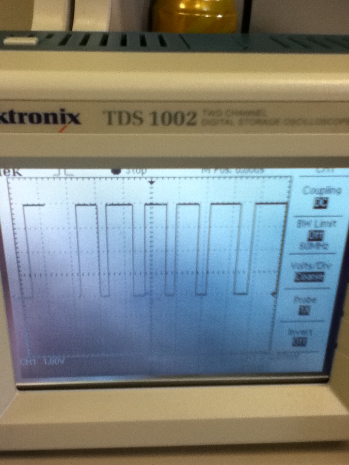
below is a picture of the wave form on the oscilloscope

Each y axis grid = 100mv Each x axis grid = 100ms
HALL EFFECT SENSOR

www.autrotronicsstudies.blogspot.com
this sensor is another type of distributor and has a magnet and a integrated circuit which picks up the magnetic field. when the rotor spins through the signal between these to objects it has broken the magnetic circuit and it collapses.
this sensor has 3 wire inputs
- 5 volt input
- ground
- output signal
I then hooked up my sensor to a 5 volt battery supply on the 5 volt input wire and the ground wire.
i then put my voltmeter on the output signal wire and the ground wire.
Once i had hooked these up, i then turned the gear to different angles, every 45° up to 180° and recorded my data:
| Degrees Turned | Voltage |
| 0° | 1.08v |
| 45° | 4.5v |
| 90° | 1.08v |
| 135° | 4.5v |
| 180° | 1.08v |
when my reading was 1.08v it was because the rotor was in the way of the integrated circuit and when my reading was 4.5v it was because there was nothing in the way of the integrated circuit.
i then hooked up an oscilloscope to this sensor and recorded a graph to get specific data on what the voltage was doing:
as the rotor goes between the integrated circuit the voltage goes strait down and as it passes through, the voltage goes strait up again, there is no slope because it cuts off strait away.
OPTICAL DISTRIBUTOR

www.vic-4826.blogspot.com
This sensor works by sending an infa-red signal to a photo electric pick up, when the the chopper blade spins around it blocks the signal and breaks the circuit.
There is 3 wires that this sensor has
-5 volt input
-earth/ground
-signal output to ecu
when the chopper plate is in the way of the infa-red signal, the distributor is firing. when the blade is not in the way, it is changing up.
below is a table of results i recorded when i hooked up a 5 volt battery supply to the input and ground wires and multimeter to the output signal and ground wires.
i rotated the gear on the distributor to certain angles and measured the voltage output to the ecu.
| Position | Voltage |
| 0° | 0.5v |
| 30° | 4.5v |
| 60° | 0.5v |
| 90° | 4.5v |
| 120° | 0.5v |
when the voltage is 0.5v, it is when the chopper plate is blocking the infa-red signal and no voltage is being passed through to the photo electric pick up.
when the voltage is 4.5v, it is when the chopper plate is not blocking the infa-red signal and the circuit is being aloud to pass be completed.
i wired up an oscilloscope to the sensors output and ground wires, i also had the 5 volt battery supply wired up to the input and ground wires.
below is a recording of what the oscilloscope was reading:

as you can see. when the wave is up , this is when the chopper plate is not covering the signal but then when it quickly drops, that is when it is being covered by the chopper plate.
The hall effect and optical sensor both put out an easy to mange digital signal but the magnetic sensor puts out an analogue signal which has to go through analogue to digital converter.
all of these sensors are located on the distributor at the tip of the cam shaft but the optical and hall effect sensors can be used as crank angle sensors also.
(I then hooked this sensor up to a 5 volt input supply and a ground.)
ReplyDeleteInductive DOESN'T HAVE A 5V INPUT!
Hall
(Once i had hooked these up, i then turned the gear to different angles, every 45° up to 180° and recorded my data:)
This can't be 45 degrees because there is a start and stop to each blade(cutter), even your pattern picture shows it is not 45 degrees
Optical
Is this really 30degrees each change in the pattern?