Thursday 16 June 2011

Scan Tool Diagnosis

for this exercise i let the engine run at idle

the engine was a 1ZZ-FE

i plugged the diagnosis plug into the engine diagnosis port, answered all the questions about the engine details and then recorded my data

below is a table of live data from the engine


Type of information Letters to describe Value of data units
how much air comes in MAF 2.55 Gm/s
Engine RPM engine speed 700 RPM
Throttle angle TPS 11 %
Engine coolant temperature ECT 73
intake air temperature IAT 22
Fuel injection opening pulse injector pulse time 2.7 ms
transmission select position shift 4
vehicle speed 0 0 km/h
oxygen sensor O2 0.79 V
fuel trim short term fuel trim -20.3 %
idle control IAC 37.5 %
power steering condition pwr steering NA
air conditioning condition air con NA
malfunction indicator light engine warning light on on


my lecturer then put a fault in the engine and i looked the codes up in the scan tool.

code number - P0120
System affected - TPS
Condition described - circuit malfunction

i then checked the parameter identification

the value of data was 0%

i then did a visual inspection of the sensor to see if there was anything visually wrong with it

i did this by checking the wires and making sure the voltages were correct readings

after checking the ground wire and output to ecu, i found that the reference voltage was out of spec. i checked this by checking the voltage coming out of the ecu for the 5v reference and found out that it was not reading 5 volts

i then cleared the codes using the scan tool, i then turned the key off and then back on and found that the codes had been cleared.

a scan tool is useful because it tells you where to look for the problem on the engine, however you still need to know how to fault find on the component.

Wednesday 15 June 2011

Exhaust Gas Analysis

to record the following data i placed the exhaust analyser into the exhaust pipe of the vehicle.

Carbon Monoxide (CO) - if the engine is putting out these gasses, the catalytic converter is not working correctly. with a high number, the catalytic converter is not working properly.

Hydro Carbons (HC) - with his gas, we can tell about the misfires in the engine.

Carbon Dioxide (CO2) - this gas will show us if the catalytic converter is working correctly. with a high number, this will tell us that the catalytic converter is working correctly.

Oxygen (O2) - these levels will show us if the engine is running too ritch or too lean. if the oxygen levels are high, the engine is running lean. if the oxygen levels are low the engine is running too ritch.

i then went ahead and let the analyzer run its course and test the emissions when the engine was idling cold and recorded the four gasses

CO - 41% - this shows us that the cat is not working because these gasses are quite high.
HC - 340ppm - this shows us that the engine is misfiring a lot
CO2 - 12% - these levels are quite low, this shows us that the cat is not working correctly.
O2 - 0.6% - this shows us that the engine is running that the engine is running ritch.

i then let the engine warm up to operating temperature and recorded the four gasses again.

CO - 3% - this shows me that the cat is still not working correctly because this number should almost be 0
HC - 171ppm - this shows me that there is not as many misfires in the engine because the number has dropped.
CO2 - 12.8% - this is quite low which still indicates that the cat is not working correctly
O2 - 0.08% - this shows me the engine is running even more ritch than at idle.

after the previous test i let rev'd the engine up to 2500 rpm and recorded the four gasses

CO - 39% - this tells us the cat is still not working and needs replacing because this gas should not be getting released.
HC - 245 ppm - this shows that as the engine is rev'd up, is gets an increase in misfires
CO2 - 12.8% - this is still low which indicates the cat is broken.
O2 - 0.18% - this number has gone up quite a bit which tells us the engine is running a little bit lean.

with the results of these tests, it is clear that the catalytic converter is broken and not filtering the gasses, it also tells us that the engine has misfire.
the carbon monoxide was too high and is very harmful to breathe in.

Tuesday 14 June 2011

Oscilloscope Patterns to Capture

Engine Coolant Temperature Sensor

i hooked the engine up to an oscilloscope and then let it idle while is was cold and kept reading the oscilloscope while it was heating up


in the above oscilloscope reading, you can see as the line is at the higher point it is cold and when the engine starts warming up the line starts going down, this means the voltage is dropping.

this reading could be faulty if the sensor had a bad earth or a faulty thermistor this could cause the engine to over heat.


MAP Sensor

For this sensor i hooked up the oscilloscope up to the output wire and to the ground wire i then gave then engine a few quick revs

when i snapped the accelerator i found that the voltage went up because there was no vacuum and when i had the engine at idle there was not much voltage because there was full vacuum.

is the sensor was giving a faulty reading it could be because there is a bad earth or the vacuum line is not on properly or leaking.

if the hose was leaking or not attached the sensor would be reading no vacuum so it would tell the ecu to squirt maximum fuel into the combustion chamber.


Throttle Position Sensor

with this TPS i did not turn the engine on but switched the ignition on, i hooked the oscilloscope to the output wire and the ground wire.

i then paused an image of the oscilloscope reading once i had done a half throttle position and a wide open throttle position.

below is the picture of the oscilloscope reading that i have drawn.


at point A, this is when the engine is at idle. point B is when i put the throttle half open, point D is when i put wide open throttle.

if the TPS was giving a wrong reading it could be because the sensor was not grounded properly or a terminal is loose. the sensor could also be faulty.

this would send the wrong voltage to the ecu which would tell the injectors to stay open too long or too short, this would not let engine run correctly for drivers needs.


Intake Air Temperature

this sensor works the same way as the coolant temperature sensor. the higher the temperature, the lower the voltage.

i hooked up this sensor to the oscilloscope on the output wire and the ground wire.

to make the temperature go up on the intake, i got a heat gun and slightly raised the temperature so i could get a visible reading.

as i put the gun into the intake, the voltage begins to drop.

if the sensor was giving an incorrect reading, it could be because the sensor is not grounded properly or has a faulty thermistor in it.


RPM Cam


for this test i let the engine idle and hooked up the oscilloscope to the output wire and a good ground.

below is a recording of what the oscilloscope reading looked like


as you can see, cylinder 1 is not recognized as the other 3 cylinders, this is because the ecu needs to recognize how fast the cam is spinning because this is what the engine timing gets its readings from.

if the sensor was giving faulty reading the engine would run advanced or retarded depending on what voltage is being sent to the ecu. this could mean a bad earth or faulty sensor that needs replacing.


RPM Crank

this sensor was recorded at idle and had the oscilloscope hooked up to the output wire and a good ground

below is a drawn reading of the oscilloscope reading

as the waveform is at its peak, the cog gear is closest to the pick up sensor when the wave form is at its lowest point, the cog tooth is furthest away from the sensor. this tells the engine how many RPM's it is doing by sending the signal to the ecu.


Oxygen Sensor

i hooked this sensor up to the oscilloscope on the output signal and good ground.

i then let the engine idle and watched the waveform change by a small difference.

below is a drawn picture of what the waveform looked like on the oscilloscope


as the waveform goes slightly up, this means the engine ran slightly ritch and the O2 sensor voltage went up which told the ecu to make it run a bit leaner, its then increased which the sensor told the ecu again and it ran even more lean which evened out the idle when it oscillates back to normal voltage.

Fuel Pressure and Flow

the fuel pressure and flow are one of the most important parts of the injection system, this depends on how much fuel gets squirted into the injectors.

before i started this test, i checked the specifications of the fuel pressure for this engine (4A-FE). the pressure was 38 to 44 PSI. I then did a visual check to make sure there was no leaks in the system.

i then measured the fuel pressure of the engine with the ignition on but the engine off, there was no pressure because the engine had not been on.
then i turned the engine on and let it idle for a few minutes and found the pressure raised to 36 PSI.
after that i clamped the fuel return line to find that the pressure went off the scale to above 87 PSI.

the next test i did, i took off the vacuum line and blocked it so the engine thought it was at wide open throttle, this brought the pressure to around 45 PSI.
i then turned the engine off but left the key on and watched the pressure drop to 37 PSI, this is the residual pressure.


if the engine had low fuel pressure the vehicle would have a rough idle and be running lean, this would happen because the injectors would not have enough pressure to squirt the right amount of fuel into the combustion chamber. this could mean that the pressure regulator not letting fuel rail build enough pressure and could be stuck open or a faulty fuel pump.

If the engine had a high fuel pressure, this would mean the vehicle would have a boggy idle because the engine would not be burning the fuel properly, this would be creating carbon monoxide. the injectors would be squirting too much fuel into the combustion because the pressure would be too high, this could also cause the injectors to dribble. this could mean the pressure regulator is stuck closed and not allowing pressure out into the return line.

Sunday 12 June 2011

Primary & Secondary Ignition patterns

Primary Voltage Patterns

in this exercise i set up an oscilloscope to look at the primary ignition pattern of my engine while it was idling and warmed up (closed loop)
i rigged this oscilloscope up by putting the positive feed from the scope onto a pin which was inserted on the input down the connector of the distributor, i then put the negative/ground wire on a good common earth.

below is a table of the recordings i collected from the ignition patterns:


Cyl 1 Cyl 2 Cyl 3 Cyl 4 Primary Ignition
248v 248v 248v 248v Firing Voltage
55.6v 55.6v 55.6v 55.6v Burn Voltage
1.48ms 1.48ms 1.48ms 1.48ms Burn Time
6.2ms 6.2ms 6.2ms 6.4ms Dwell Time


volts per division = 50v              milli seconds per division = 2ms


if we follow the line across the screen (left to right), when the line drop, this is called the DWELL TIME, this is when the circuited is grounded.
when the line is at its peek and goes all the way up, this is called the FIRING VOLTAGE, this is the voltage that it takes to push through the high tension leads and to spark plug.
when the line drops down and slightly scribbles across, this is the BURN TIME, this is the time we use to keep sparking the so we can burn all fuels in the combustion chamber.
when the line goes back down but oscillates, this is because the magnetic field is taking time to release.

The raster and stacked display you can put the patterns on top of each other, this helps to to compare times better and makes it more clear to see the length of things.


Secondary Voltage Patterns

in this exercise i had to set up an oscilloscope to the secondary ignition. i did this by attaching a belt around the distributor, this would sense the voltages through the distributor cap, i also rigged up a common earth.

i then let the engine idle at operating temperature and recorded my reading and put them into a graph.


Cyl 1 Cyl 2 Cyl 3 Cyl 4 Secondary Ignition
5.4kv 8.2kv 5.9kv 6.2kv Firing Voltage (killer volts)
0.75ms 0.87ms 0.65ms 0.71ms Burn Time (milli seconds)
9.8kv 8.4ms 9.8ms 9.0ms Snap acceleration


this waveform is the same as the primary waveform, the only difference is that the secondary pattern does not have a dwell time..
 the results from this test are all good and within specifications of the engine type (4A-FE)
when i snapped the accelerator i expected the burn time to be longer because it had more fuel inside the combustion chamber to burn, therefor the burn time needed to increase so it could burn all of the gasses .


Shorted Secondary


Cyl 1 Cyl 2 Cyl 3 Cyl 4 Secondary ignition
5.4kv 3.2kv 5.9kv 6.2kv Firing Voltage (killer volts)
0.75ms ____ 0.65ms 0.71ms Burn Time (milli seconds)

in the above table i have shorted number 2 cylinder to ground and it has a lower firing voltage because it has less resistance to make it fire.

Below is the waveform drawn from the oscilloscope:


the peek firing voltage says 10 volts but it is really 3.2kv

there is only a firing voltage on the graph because there is not any burn time to read on the oscilloscope because the plus is not in the cylinder.


Spark Tester

the spark plug tester is like a spark plug that goes on the end of a HT lead, this lets us know if the spark plug in engine is faulty or the plug gap is too large or too small

if the gap was too big, the burn voltage would be a lot higher and if the gap was too small the burn voltage would be a lot smaller. this happens because it takes more voltage to push the electricity across the spark plug gap if it is bigger. if it is smaller it takes less voltage.

Flash Codes

Flash/Blink codes
If the check engine light was on when the ignition is on, there is a fault in the system some where.
for this test i read the workshop manual and found out that i needed a jumper wire to find out theses faults. i had to connect the jumper wire to two terminals in the fuse box and join them together (TE1 and E1).
When i connected the jumper wire to the two terminals, the check engine light would then start flashing and make a pattern that i had to look up in the manual to find out what they mean.

For example: if the light flashed 2 times and then 4 times. i would look up the number 24 in the manual.

Trouble codes or Fault codes
below is a table of recordings that came up as faults on my engine when the tutor made some faults for me to find.


Code Number System Affected Condition Described
24 air intake temp incorrect air fuel ratio
31 vacuum sensor too much fuel being squirted in
41 TPS bad idle RPM


Visual Inspection to find fault and repairing fault
-air intake temp sensor was unplugged when i had a look at it, to repair this i plugged it back in
-vacuum sensor was unplugged when i checked it, i then plugged it back in.
-TPS sensor was also unplugged, to repair this i had to plug it back in.


Clear Codes and Recheck for them
i turnedd the ignition off after i had fixed the faults, this also  clears the codes.
when i turned the ignition back on the check engine light was off and there were no faults in the system.

How could the faults affect engine performance?
these faults would have made the engine not idle correctly and eventually blow up because of the pinging, this was due to the vacuum sensor being unplugged which made the ecu think that it was at wide open throttle so it was putting maximum fuel in.

After the engine light is off i should do another visual check to make sure everything is plugged in properly and the engine is running correctly.

Practice Back-Probing

review of multimeter
First of all, i turned on my meter and set it to ohms. i then made sure that the probes were not touching each other and i got a reading (OL) this reading means that there is an open circuit.

reading ohms with wires connected
i set my multimeter to ohms and touched the two probes together. the reading i got was 0.4 ohms, this is the resistance in the circuit. this is quite a high recording from a multimeter, it should generally be around 0.2 or less.

practice back probing connectors
for this test i used a hard shell connector and gently probed a pin into the connector so it fits beside the wire and then i put my multimeter prong onto the pin, i then put my other multimeter prong through the other side of the connector and recorded the resistance. the reading i got was 0.5 ohms.
this was a good connection because it was a solid reading and the numbers weren't jumping up and down, also if i had a bad connection the resistance would be higher.

Thursday 9 June 2011

input sensors and actuators

Injector input
the voltage to the fuel injector was 5 volts, i checked this by putting a pin down the input signal wire carefully. i then used my voltmeter and recorded 14 volts to the injector.

we check the fuel injector voltage so we know that they a getting proper voltage to them and opening properly.
if the injector was getting a lower voltage than normal the engine would not be getting a proper amount of fuel and would not be running correctly because the injectors would not be opening as much as they should be.

below is a circuit diagram of the injectors:


TPS input


the 5 volt input wire to this sensor was yellow.
the purpose of this wire is to provide voltage to the sensor, if the sensor was not getting a full 5 volts it would not be sending a good reading to the ecu and the engine would not be running at its peak performance.

Ground at TPS sensor

the voltage at the earth wire of this sensor was 0.002v. this is a good voltage to have because it means that there is very little resistance in the circuit and all connections are good.
If the voltage across the earth wire was high, it is likely that there would be a loose connection or some sort of resistance in the circuit.

TPS output

the voltage of the output of the sensor when the throttle is closed was 0.38v.
when i opened the throttle half was the output voltage was 2.23v.
when i opened the throttle all the was the voltage output was 3.78

I then slowly opened the throttle and made sure my voltage slowly went up without any glitches, this means that my TPS is smooth with no carbon build up.

I located the "idle switch wire" and it was around 0v when the throttle was closed, then when i opened the throttle all the way i got around 12.4 volts

I got all of these reading using my voltmeter, set to 20volts dc. i had common earth and then i put my positive probe in each of these wires.

this sensor was a switch type because it gives a reading when the throttle is closed and fully open.

some of the things that could of given the ecu a wrong output signal is:
bad earth connection
faulty input voltage

below is a drawn circuit diagram of the TPS circuit:


ECT Sensor

When i measured the supply voltage for the ECT sensor i measures 3.58v, i measured this when the engine was at normal operating temperature, this seemed like a reasonable reading according to the data sheet.

when i started the engine found that the voltage lowered to 1.1v as the engine got a little bit hotter.

At colder temperatures the ECT sensor sends a higher voltage to the ecu which tell the injectors to stay open longer to squirt more fuel into the combustion chamber so  the engine can warm up faster.

the ecu could get a wrong voltage if the thermistor in the sensor was fault or there was a bad ground connection.


Ground coolant temperature sensor

When i located the ground wire, the voltage was 0.1mv, this tells that it is a good ground and the ecu will get a accurate reading from the sensor.
If the ground wire was not good, the ecu would get faulty reading and could make the engine to ritch or lean.

below is a drawn diagram of the ECT circuit:


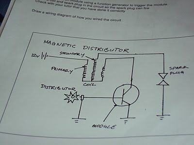
RPM/ Crank Angle Sensor


for this test i set my multimeter to AC volts

i turned on the engine and measured the signal wire voltage and i got 90mv,
when i increased the revs to 2500 rpm i got 197mv

For this test i set my multimeter to DC volts

with the engine at idle speed i was getting a reading of 1.2v
i then increased the rpm to 2500 and got a reading of 1.6v

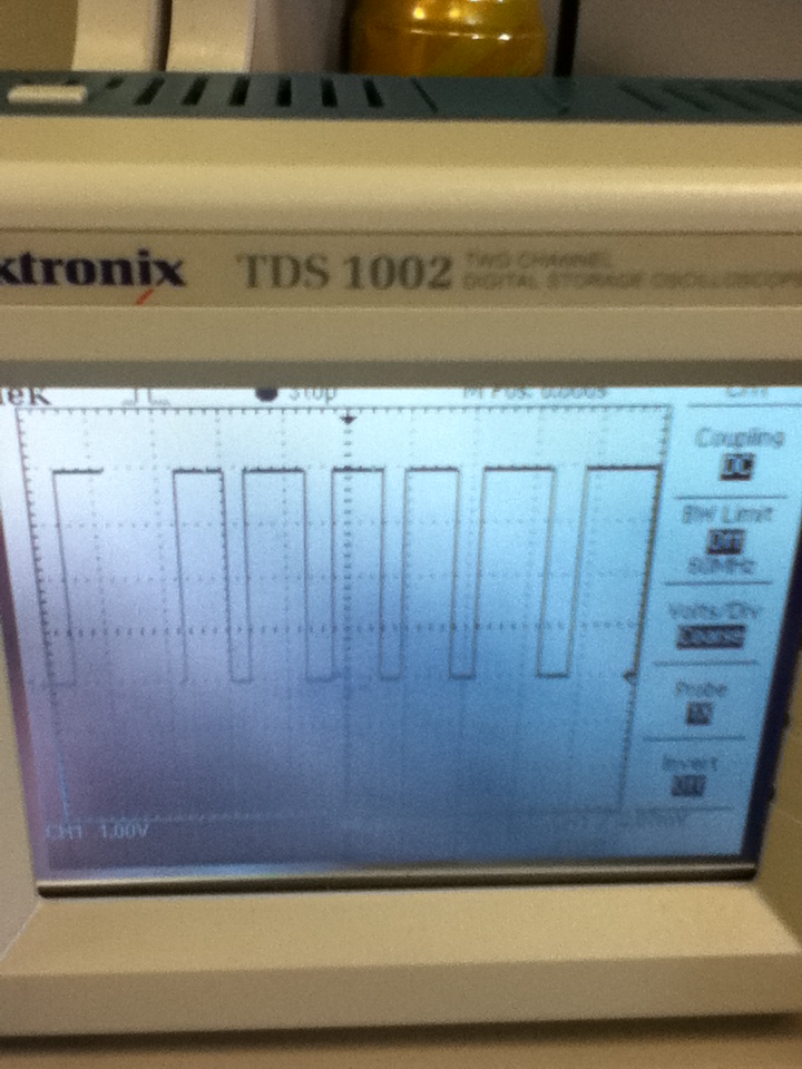
For this test i set my multimeter to Hertz

at idle i recorded 5kHz
i then increased the speed to 2500rpm and recorded 7.5kHz

for all of the above tests i set my multimeter to the required setting, i also had the same common ground and put my positive probe into the signal wire input.

i think that AC volts gave the best reading because i could really see the voltage go up when i changed the RPM

changing the the functions on your multimeter can help because it helps you to get a better picture of what your signal is doing.

If the ecu did not receive the correct signal from this sensor the engine would not properly because this is the most important sensor as it tells the others what the conditions are.

below is a drawn diagram of the sensor:


MAP sensor


when i found the input wire to the map sensor i was told to measure the reading using volts DC, the reading i got was 1.8v, this was with the ignition on but the engine not running.
i then started the engine and got a reading of 0.48v.
I then gave the engine a short acceleration and recorded 1.8 volts.

this shows my reading are correct because when the throttle is closed there is full vacuum because no pressure can get in so the input voltage is low and then when the throttle gets opened, there is no vacuum so the voltage gets higher.

if the ecu received the wrong signal from the MAP sensor it would tell the injectors to stay open too long or too short and could make the engine run too ritch or too lean.


IAT Sensor


For this sensor i found the input wire and measured the voltage DC with the ignition on but the engine not running. i recorded 3.3v.
this voltage is less than the ECT sensor input, this shows that the IAT sensor is hotter than the ECT sensor

the air intake temperature affects the ecu outputs for the fuel injection because it works out the temperature of the air and tells the injectors to squirt "x" amount of fuel in to atomize the fuel better.

the IAT has a thermistor inside it which lowers its resistance as it gets hotter this means there is more volt drop across the second resistor which puts out a lower voltage.

the ecu can get an incorrect reading if the sensor gets damaged or dirt caught in it.


Camshaft Position Sensor


for this task i was told to record different functions and discuss which of the function show the sensor is good.

DC volts = 19.5mv
AC volts 1.2v
Hertz = 0.09kHz
Duty cycle = 14%

I think that AC volts tells me that the sensor is working because it has a good input voltage.

Wiring Up Ignition Systens

ignition module pinouts:

C = Coil (connect to coil negative side)                                                                              
EXT = connect into negative post of power supply
B  =  connect to positive post of power supply
T  = connect to red wire from function generator
F  =  feedback (leave it free)


FIRST IGNITION CIRCUIT


i then had to draw the circuit diagram:


as you can see there is a 12 volt battery supply, this goes into the primary side of the windings in the coil and charges up the secondary windings.
this then comes out of the other primary side of the coil and into the ignition module.
the function generator then sends a pulse to the ignition module which grounds the circuit.
the secondary windings are also grounded and are able to spark the spark plug.


SECOND IGNITION CIRCUIT


i then had to draw this diagram :


in the diagram above the 12 volt battery supply goes into the primary side of the coil and charges up the secondary.
the other side of the primary windings goes down into the ignition module and as the distributor spins around, the ignition module grounds the circuit and the secondary winding releases its spark and sparks the plug.


THIRD IGNITION CIRCUIT


I then drew circuit diagram of the above circuit:


i the above diagram, the 12 volt battery supply goes strait to the firing spark plugs but can only fire when the function generator sends a pulse to the igniter and grounds the circuit. this will then allow both spark plug to fire.


FOURTH IGNITION CIRCUIT


i then was asked to draw a diagram of the circuit:


in the above diagram, the 12 volt battery goes to the primary side of the coil which charges up the secondary windings. this will not spark until the function generator grounds it and sends a pulse.


Wednesday 8 June 2011

Speed/Posistion Sensors (off car)

Magnetic reluctor sensor


www.evgen-autotronics.blogspot.com


this sensor has a stationary magnet that has a metal gear with teeth spinning around and every time a tooth passes by the magnet it charges up the winding by the magnet. when the tooth moves past the magnet, the voltage in the winding collapses.

to service this sensor you have to check the air gap between the teeth and the magnet with a brass feeler gauge.


the specifications on the distributor i had were that the air gap had to be between 0.2-0.4mm. i measured 0.3mm so my distributor was is within specification

I then hooked this sensor up to a 5 volt input supply and a ground. i then also hooked up my oscilloscope to the output and ground.
as i turned the gear on the sensor, and the the teeth move towards the magnetic pickup. the voltage slowly went up and down in a wave form ranging from up to 492.7mv


below is a picture of the wave form on the oscilloscope

Each y axis grid = 100mv       Each x axis grid = 100ms


HALL EFFECT SENSOR


www.autrotronicsstudies.blogspot.com


this sensor is another type of distributor and has a magnet and a integrated circuit which picks up the magnetic field. when the rotor spins through the signal between these to objects it has broken the magnetic circuit and it collapses.

this sensor has 3 wire inputs
- 5 volt input
- ground
- output signal

I then hooked up my sensor to a 5 volt battery supply on the 5 volt input wire and the ground wire.
i then put my voltmeter on the output signal wire and the ground wire.

Once i had hooked these up, i then turned the gear to different angles, every 45° up to 180°  and recorded my data:


Degrees Turned Voltage
1.08v
45° 4.5v
90° 1.08v
135° 4.5v
180° 1.08v

when my reading was 1.08v it was because the rotor was in the way of the integrated circuit and when my reading was 4.5v it was because there was nothing in the way of the integrated circuit.

i then hooked up an oscilloscope to this sensor and recorded a graph to get specific data on what the voltage was doing:


as the rotor goes between the integrated circuit the voltage goes strait down and as it passes through, the voltage goes strait up again, there is no slope because it cuts off strait away.


OPTICAL DISTRIBUTOR

www.vic-4826.blogspot.com


This sensor works by sending an infa-red signal to a photo electric pick up, when the the chopper blade spins around it blocks the signal and breaks the circuit.

There is 3 wires that this sensor has
-5 volt input
-earth/ground
-signal output to ecu

when the chopper plate is in the way of the infa-red signal, the distributor is firing. when the blade is not in the way, it is changing up.

below is a table of results i recorded when i hooked up a 5 volt battery supply to the input and ground wires and multimeter to the output signal and ground wires.
i rotated the gear on the distributor to certain angles and measured the voltage output to the ecu.

Position Voltage
0.5v
30° 4.5v
60° 0.5v
90° 4.5v
120° 0.5v

when the voltage is 0.5v, it is when the chopper plate is blocking the infa-red signal and no voltage is being passed through to the photo electric pick up.
when the voltage is 4.5v, it is when the chopper plate is not blocking the infa-red signal and the circuit is being aloud to pass be completed.

i wired up an oscilloscope to the sensors output and ground wires, i also had the 5 volt battery supply wired up to the input and ground wires.

below is a recording of what the oscilloscope was reading:


as you can see. when the wave is up , this is when the chopper plate is not covering the signal but then when it quickly drops, that is when it is being covered by the chopper plate.


The hall effect and optical sensor both put out an easy to mange digital signal but the magnetic sensor puts out an analogue signal which has to go through analogue to digital converter.

all of these sensors are located on the distributor at the tip of the cam shaft but the optical and hall effect sensors can be used as crank angle sensors also.

Oxygen sensor (off car)

oxygen sensor


this sensor is one on the most important sensors of the modern engine, it tells the ecu if the engine it tells the ecu if the engine is running ritch or lean.
the sensor is not being used during warm up because the engine is in open loop. this means that the injectors are squirting a specific amount of fuel into the combustion chamber during engine warm up.
once the engine reaches its ideal running temperature (depending on manufacture, around 300°C) this is when the oxygen sensor is warmed up and starts sending signals to the ecu (closed loop)

this sensor may have 1 to 4 wires depending on manufacture:
signal wire
ground wire
heater positive
heater ground

if the engine is running to lean the output to the ecu will be around 0.2 volts and if the engine is running too ritch the output to the ecu will be around 0.8 volts (depending on manufacture)

Knock Sensor

knock sensor

www.iapdirect.com

this sensor has a piezoelectric device that creates its own voltage when it gets shaken.
this voltage gets sent to the ecu which will change the timing to stop the knock from happening.

This sensor has 2 pins (earth and a 5 volt input). it doesn't matter which pin is used.
i put an oscilloscope on these pins and knocked the sensor on the table, this is the wave form picture i recored.

Engine Coolant/ Air Temperature Sensor (off car)

engine coolant/ air temperature  sensor


www.elise-shop.com


the coolant and air temperature are the same and are both a NTC type (negative temperature coefficient), this means that when the temperature rises, the resistance in the sensor will lower. this means that is will send a higher voltage to the ecu when the engine gets hot (operating temperature).
Generally there is a 5 volt input to the sensor and when the engine is cold, the output to the ecu is around 1 volt, when the engine is at operating temperature it is around 4.5 volts.


www.wiringdiagrams21.com

The 2 prongs on the sensor are a earth and a 5 volt input (doesn't matter which)
This works by changing the voltage output the the ecu receives by changing the resistance as the temperature changes.

TESTING COOLANT TEMP SENSOR
to test this sensor i heated up some water in a bowl starting at 33°C and ranging up to 75°C.
as the temperature increased i measured the resistance between the two windings of the sensor which was decreasing as it got hotter.

i then recorded some data at different temperatures of the sensor:


Water Temperature Resistance
33°C 1.36 k ohms
35°C 1.33 k ohms
40°C 1.14 k ohms
45°C 0.96 k ohms
50°C 0.78 k ohms
55°C 0.68 k ohms
70°C 0.46 k ohms
75°C 0.39 k ohms


TESTING AIR TEMP SENSOR

when i tested this sensor i also got a bowl and heated up the water, i started at room temperature and then put it in the bowl which was up to 55°C.

to measure the resistance i put my ohmmeter on the two prongs of the sensor and recorded my readings:


Temperature Resistance
room temp 1.81 k ohms
35°C 1.57 k ohms
40°C 1.23 k ohms
45°C 1 k ohms
50°C 0.87 k ohms
55°C 0.71 k ohms

Monday 6 June 2011

MAF sensors (Mass Air Flow) On/Off car

OFF CAR

Hot Wire Airflow Sensor

Note: i did test this type of sensor.


www.autospeed.com


This sensor has 3 main wires (5volt power, earth, analogue signal)
when the engine is at idle and the throttle butterfly is closed the output voltage of the sensor is around 1 volt. When the throttle butterfly is fully open the output voltage of the sensor is around 4.5 volts.
To test this sensor you must set your voltmeter to read 20 volts and place your negative probe on the earth wire of the sensor and your positive probe on the output signal wire of the sensor.
you must then hook up a 5 volt battery supply to the 5 volt power terminal and the earth terminal.
once you have done this, you need to get a hair dryer or something to blow into the sensor the give you different voltage readings.

This has a thermistor inside of it and when the revs go up increasing the airflow, the thermistor cools down and makes the resistance lower. this means there is more voltage to ecu which tells us the throttle is opening more.


Vane/Flap type air flow sensor


www.kjfgb-hteyc.tk


this type of airflow meter has also got 3 main wires (5 volt input, output, earth)
to test this sensor you must set your voltmeter to 20 volts, place your negative probe on the earth terminal, place your positive probe on the output terminal. you must then have 5 volt battery supply to the input terminal and the also connect it to the earth if the sensor.
once all of these thing are hooked up slowly move the flap on the inside of the sensor, your voltage should slowly go up.
when the flap is closed it thinks the engine is at idle and is only sending 1 volt to the ecu, when the flap is fully open it thinks the engine is at open throttle sending around 4.5 volts to the ecu.

i created a graph at the different angles i had the flap open at and the voltages i was reading:


vane angle voltage output
2.2V
20° 4.7V
40° 6.8V
60° 7.6V
80° 8.1V
100° 8.5V
120° 9.4V

as the flap opens more, it creates a greater voltage output to the ecu

MAP sensors (on/ off car)

OFF CAR

The MAP sensor (manifold absolute pressure) senses how much vacuum there is inside the inlet manifold, when there is more vacuum, there is less output voltage to the ecu. when the sensor is reading a low vacuum there is a higher voltage to the ecu. When the throttle is wide open the sensor will be reading a very low vacuum because all of the pressure is being sucked into the engine, this means the manifold can not build up enough pressure to give a big reading to the ecu so it sends a small voltage, this makes the fuel injectors stay open for longer to put more fuel into the engine.

When the throttle is closed then engine is building up vacuum because not much pressure can get into the manifold, this means that the engine vacuum is sucking and the vacuum inside the manifold gets bigger creating a greater voltage to the ecu, this means the engine is at idle and will tells the injectors to stay open for only a short amount at a time to limit the fuel into the combustion chamber.

www.atspeedracing.co.uk


The Map sensor has a input for a tube where it get the vacuum from the manifold. it has 3 terminals on it (5 volt input, earth and a output voltage that it sends to the ecu)

To test this sensor i had to use a devise that creates vacuum and put it onto the vacuum tube input. I then had to give the sensor a 5 volt battery supply which i hooked up to the 5 volt terminal, i also put the negative clip of the battery supply to the earth terminal of the sensor. Once i did that i measured the voltage output with my multimeter, i set it to read around 20 volts and then placed my positive prong on the output pin of the sensor and my negative prong on the earth terminal of the sensor.

below is a picture of the devise i used to apply vacuum to the sensor:

www.autotechnique.fr


the more vacuum i applied, the less the voltage output to the ecu

Wednesday 1 June 2011

throttle position sensor (off car)

Potentiometer Type:

this sensor has a sliding contact that moves every time the throttle is moved. the sensor is supplied a voltage by the ecu and as the throttle moves it creates a bigger voltage output (idle is around 0.5 volts and wide open throttle is around 4.5 volts)


i connected my sensor to a 5 volt supply and measured the angles i set it at.
i then used my volt meter to check the voltage output that the sensor was giving, i did this by putting my negative probe on the "ground" pin out on the sensor and putting my positive probe on the "output' pin out on the sensor. each time i changed the angle of the throttle butterfly i got a different reading which increased as i opened throttle wider.


Throttle Angle Voltage Output
0.714V
22.5° 1.15V
45° 1.96V
67.5° 2.76V
90° 3.86V

I then created a table to record my data:


this table shows that the wider i opened the throttle, the higher the voltage output.


Switch Type:


this throttle position sensor is a switch type, it usually only has two contact points (wide open throttle and closed throttle). it generally has three pins (idle, voltage in, full throttle)

to test this sensor you need to check the resistance, you do this by putting your negative prong on the earth pin and your positive prong on the idle pin (make sure throttle is closed), you should get a very minimal reading around 1.4ohms.
you then place your positive prong on the wide open throttle pin (make sure the throttle is wide open) your should also get a very minimal reading around 1.4ohms

i recorded a graph to explain my reading better: