Thursday, 9 June 2011

input sensors and actuators

Injector input
the voltage to the fuel injector was 5 volts, i checked this by putting a pin down the input signal wire carefully. i then used my voltmeter and recorded 14 volts to the injector.

we check the fuel injector voltage so we know that they a getting proper voltage to them and opening properly.
if the injector was getting a lower voltage than normal the engine would not be getting a proper amount of fuel and would not be running correctly because the injectors would not be opening as much as they should be.

below is a circuit diagram of the injectors:


TPS input


the 5 volt input wire to this sensor was yellow.
the purpose of this wire is to provide voltage to the sensor, if the sensor was not getting a full 5 volts it would not be sending a good reading to the ecu and the engine would not be running at its peak performance.

Ground at TPS sensor

the voltage at the earth wire of this sensor was 0.002v. this is a good voltage to have because it means that there is very little resistance in the circuit and all connections are good.
If the voltage across the earth wire was high, it is likely that there would be a loose connection or some sort of resistance in the circuit.

TPS output

the voltage of the output of the sensor when the throttle is closed was 0.38v.
when i opened the throttle half was the output voltage was 2.23v.
when i opened the throttle all the was the voltage output was 3.78

I then slowly opened the throttle and made sure my voltage slowly went up without any glitches, this means that my TPS is smooth with no carbon build up.

I located the "idle switch wire" and it was around 0v when the throttle was closed, then when i opened the throttle all the way i got around 12.4 volts

I got all of these reading using my voltmeter, set to 20volts dc. i had common earth and then i put my positive probe in each of these wires.

this sensor was a switch type because it gives a reading when the throttle is closed and fully open.

some of the things that could of given the ecu a wrong output signal is:
bad earth connection
faulty input voltage

below is a drawn circuit diagram of the TPS circuit:


ECT Sensor

When i measured the supply voltage for the ECT sensor i measures 3.58v, i measured this when the engine was at normal operating temperature, this seemed like a reasonable reading according to the data sheet.

when i started the engine found that the voltage lowered to 1.1v as the engine got a little bit hotter.

At colder temperatures the ECT sensor sends a higher voltage to the ecu which tell the injectors to stay open longer to squirt more fuel into the combustion chamber so  the engine can warm up faster.

the ecu could get a wrong voltage if the thermistor in the sensor was fault or there was a bad ground connection.


Ground coolant temperature sensor

When i located the ground wire, the voltage was 0.1mv, this tells that it is a good ground and the ecu will get a accurate reading from the sensor.
If the ground wire was not good, the ecu would get faulty reading and could make the engine to ritch or lean.

below is a drawn diagram of the ECT circuit:


RPM/ Crank Angle Sensor


for this test i set my multimeter to AC volts

i turned on the engine and measured the signal wire voltage and i got 90mv,
when i increased the revs to 2500 rpm i got 197mv

For this test i set my multimeter to DC volts

with the engine at idle speed i was getting a reading of 1.2v
i then increased the rpm to 2500 and got a reading of 1.6v

For this test i set my multimeter to Hertz

at idle i recorded 5kHz
i then increased the speed to 2500rpm and recorded 7.5kHz

for all of the above tests i set my multimeter to the required setting, i also had the same common ground and put my positive probe into the signal wire input.

i think that AC volts gave the best reading because i could really see the voltage go up when i changed the RPM

changing the the functions on your multimeter can help because it helps you to get a better picture of what your signal is doing.

If the ecu did not receive the correct signal from this sensor the engine would not properly because this is the most important sensor as it tells the others what the conditions are.

below is a drawn diagram of the sensor:


MAP sensor


when i found the input wire to the map sensor i was told to measure the reading using volts DC, the reading i got was 1.8v, this was with the ignition on but the engine not running.
i then started the engine and got a reading of 0.48v.
I then gave the engine a short acceleration and recorded 1.8 volts.

this shows my reading are correct because when the throttle is closed there is full vacuum because no pressure can get in so the input voltage is low and then when the throttle gets opened, there is no vacuum so the voltage gets higher.

if the ecu received the wrong signal from the MAP sensor it would tell the injectors to stay open too long or too short and could make the engine run too ritch or too lean.


IAT Sensor


For this sensor i found the input wire and measured the voltage DC with the ignition on but the engine not running. i recorded 3.3v.
this voltage is less than the ECT sensor input, this shows that the IAT sensor is hotter than the ECT sensor

the air intake temperature affects the ecu outputs for the fuel injection because it works out the temperature of the air and tells the injectors to squirt "x" amount of fuel in to atomize the fuel better.

the IAT has a thermistor inside it which lowers its resistance as it gets hotter this means there is more volt drop across the second resistor which puts out a lower voltage.

the ecu can get an incorrect reading if the sensor gets damaged or dirt caught in it.


Camshaft Position Sensor


for this task i was told to record different functions and discuss which of the function show the sensor is good.

DC volts = 19.5mv
AC volts 1.2v
Hertz = 0.09kHz
Duty cycle = 14%

I think that AC volts tells me that the sensor is working because it has a good input voltage.

Wiring Up Ignition Systens

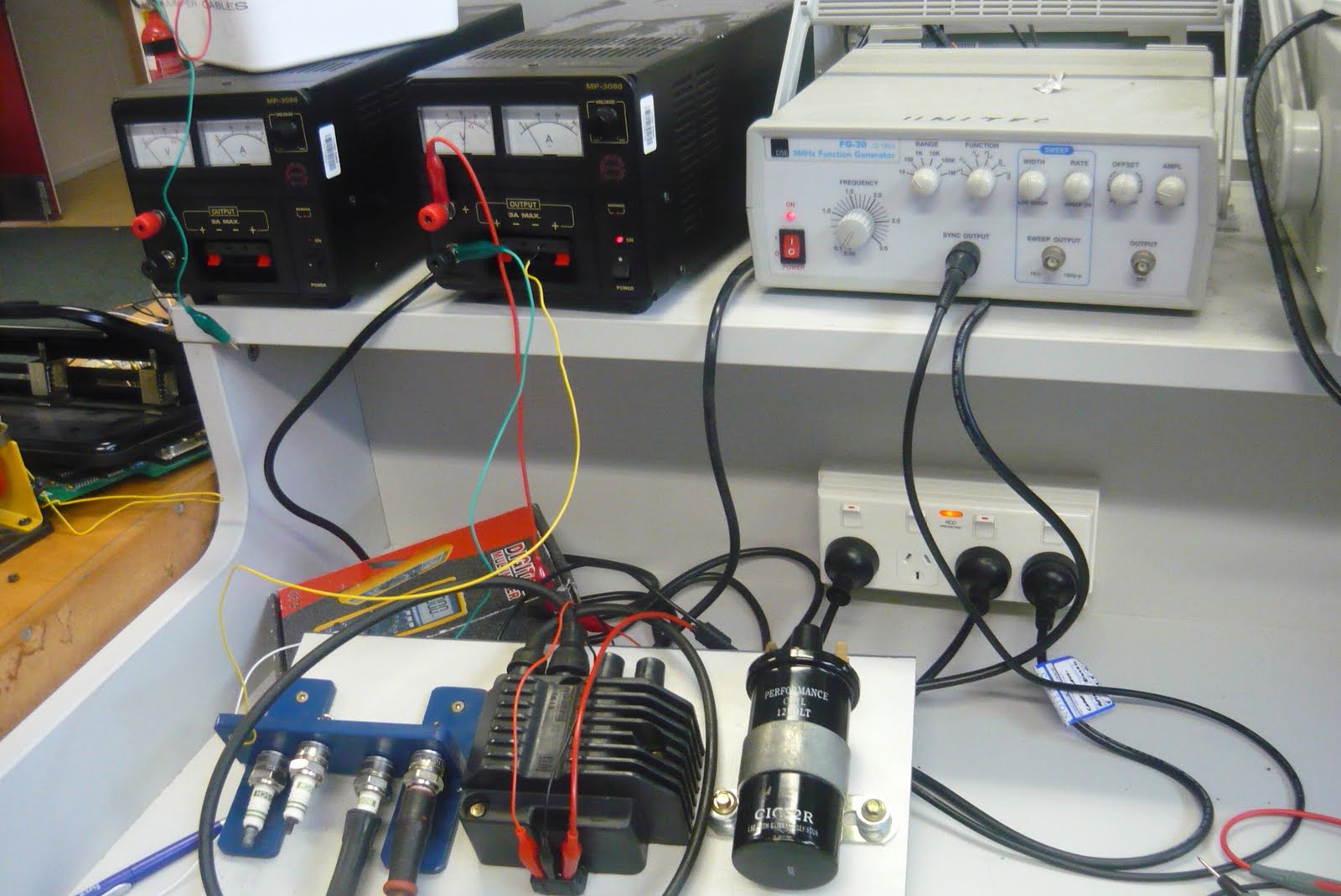
ignition module pinouts:

C = Coil (connect to coil negative side)                                                                              
EXT = connect into negative post of power supply
B  =  connect to positive post of power supply
T  = connect to red wire from function generator
F  =  feedback (leave it free)


FIRST IGNITION CIRCUIT


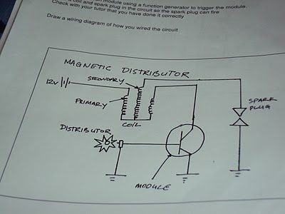
i then had to draw the circuit diagram:


as you can see there is a 12 volt battery supply, this goes into the primary side of the windings in the coil and charges up the secondary windings.
this then comes out of the other primary side of the coil and into the ignition module.
the function generator then sends a pulse to the ignition module which grounds the circuit.
the secondary windings are also grounded and are able to spark the spark plug.


SECOND IGNITION CIRCUIT


i then had to draw this diagram :


in the diagram above the 12 volt battery supply goes into the primary side of the coil and charges up the secondary.
the other side of the primary windings goes down into the ignition module and as the distributor spins around, the ignition module grounds the circuit and the secondary winding releases its spark and sparks the plug.


THIRD IGNITION CIRCUIT


I then drew circuit diagram of the above circuit:


i the above diagram, the 12 volt battery supply goes strait to the firing spark plugs but can only fire when the function generator sends a pulse to the igniter and grounds the circuit. this will then allow both spark plug to fire.


FOURTH IGNITION CIRCUIT


i then was asked to draw a diagram of the circuit:


in the above diagram, the 12 volt battery goes to the primary side of the coil which charges up the secondary windings. this will not spark until the function generator grounds it and sends a pulse.


Wednesday, 8 June 2011

Speed/Posistion Sensors (off car)

Magnetic reluctor sensor


www.evgen-autotronics.blogspot.com


this sensor has a stationary magnet that has a metal gear with teeth spinning around and every time a tooth passes by the magnet it charges up the winding by the magnet. when the tooth moves past the magnet, the voltage in the winding collapses.

to service this sensor you have to check the air gap between the teeth and the magnet with a brass feeler gauge.


the specifications on the distributor i had were that the air gap had to be between 0.2-0.4mm. i measured 0.3mm so my distributor was is within specification

I then hooked this sensor up to a 5 volt input supply and a ground. i then also hooked up my oscilloscope to the output and ground.
as i turned the gear on the sensor, and the the teeth move towards the magnetic pickup. the voltage slowly went up and down in a wave form ranging from up to 492.7mv


below is a picture of the wave form on the oscilloscope

Each y axis grid = 100mv       Each x axis grid = 100ms


HALL EFFECT SENSOR


www.autrotronicsstudies.blogspot.com


this sensor is another type of distributor and has a magnet and a integrated circuit which picks up the magnetic field. when the rotor spins through the signal between these to objects it has broken the magnetic circuit and it collapses.

this sensor has 3 wire inputs
- 5 volt input
- ground
- output signal

I then hooked up my sensor to a 5 volt battery supply on the 5 volt input wire and the ground wire.
i then put my voltmeter on the output signal wire and the ground wire.

Once i had hooked these up, i then turned the gear to different angles, every 45° up to 180°  and recorded my data:


Degrees Turned Voltage
0° 1.08v
45° 4.5v
90° 1.08v
135° 4.5v
180° 1.08v

when my reading was 1.08v it was because the rotor was in the way of the integrated circuit and when my reading was 4.5v it was because there was nothing in the way of the integrated circuit.

i then hooked up an oscilloscope to this sensor and recorded a graph to get specific data on what the voltage was doing:


as the rotor goes between the integrated circuit the voltage goes strait down and as it passes through, the voltage goes strait up again, there is no slope because it cuts off strait away.


OPTICAL DISTRIBUTOR

www.vic-4826.blogspot.com


This sensor works by sending an infa-red signal to a photo electric pick up, when the the chopper blade spins around it blocks the signal and breaks the circuit.

There is 3 wires that this sensor has
-5 volt input
-earth/ground
-signal output to ecu

when the chopper plate is in the way of the infa-red signal, the distributor is firing. when the blade is not in the way, it is changing up.

below is a table of results i recorded when i hooked up a 5 volt battery supply to the input and ground wires and multimeter to the output signal and ground wires.
i rotated the gear on the distributor to certain angles and measured the voltage output to the ecu.

Position Voltage
0° 0.5v
30° 4.5v
60° 0.5v
90° 4.5v
120° 0.5v

when the voltage is 0.5v, it is when the chopper plate is blocking the infa-red signal and no voltage is being passed through to the photo electric pick up.
when the voltage is 4.5v, it is when the chopper plate is not blocking the infa-red signal and the circuit is being aloud to pass be completed.

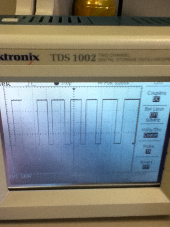
i wired up an oscilloscope to the sensors output and ground wires, i also had the 5 volt battery supply wired up to the input and ground wires.

below is a recording of what the oscilloscope was reading:


as you can see. when the wave is up , this is when the chopper plate is not covering the signal but then when it quickly drops, that is when it is being covered by the chopper plate.


The hall effect and optical sensor both put out an easy to mange digital signal but the magnetic sensor puts out an analogue signal which has to go through analogue to digital converter.

all of these sensors are located on the distributor at the tip of the cam shaft but the optical and hall effect sensors can be used as crank angle sensors also.

Oxygen sensor (off car)

oxygen sensor


this sensor is one on the most important sensors of the modern engine, it tells the ecu if the engine it tells the ecu if the engine is running ritch or lean.
the sensor is not being used during warm up because the engine is in open loop. this means that the injectors are squirting a specific amount of fuel into the combustion chamber during engine warm up.
once the engine reaches its ideal running temperature (depending on manufacture, around 300°C) this is when the oxygen sensor is warmed up and starts sending signals to the ecu (closed loop)

this sensor may have 1 to 4 wires depending on manufacture:
signal wire
ground wire
heater positive
heater ground

if the engine is running to lean the output to the ecu will be around 0.2 volts and if the engine is running too ritch the output to the ecu will be around 0.8 volts (depending on manufacture)

Knock Sensor

knock sensor

www.iapdirect.com

this sensor has a piezoelectric device that creates its own voltage when it gets shaken.
this voltage gets sent to the ecu which will change the timing to stop the knock from happening.

This sensor has 2 pins (earth and a 5 volt input). it doesn't matter which pin is used.
i put an oscilloscope on these pins and knocked the sensor on the table, this is the wave form picture i recored.

Engine Coolant/ Air Temperature Sensor (off car)

engine coolant/ air temperature  sensor


www.elise-shop.com


the coolant and air temperature are the same and are both a NTC type (negative temperature coefficient), this means that when the temperature rises, the resistance in the sensor will lower. this means that is will send a higher voltage to the ecu when the engine gets hot (operating temperature).
Generally there is a 5 volt input to the sensor and when the engine is cold, the output to the ecu is around 1 volt, when the engine is at operating temperature it is around 4.5 volts.


www.wiringdiagrams21.com

The 2 prongs on the sensor are a earth and a 5 volt input (doesn't matter which)
This works by changing the voltage output the the ecu receives by changing the resistance as the temperature changes.

TESTING COOLANT TEMP SENSOR
to test this sensor i heated up some water in a bowl starting at 33°C and ranging up to 75°C.
as the temperature increased i measured the resistance between the two windings of the sensor which was decreasing as it got hotter.

i then recorded some data at different temperatures of the sensor:


Water Temperature Resistance
33°C 1.36 k ohms
35°C 1.33 k ohms
40°C 1.14 k ohms
45°C 0.96 k ohms
50°C 0.78 k ohms
55°C 0.68 k ohms
70°C 0.46 k ohms
75°C 0.39 k ohms


TESTING AIR TEMP SENSOR

when i tested this sensor i also got a bowl and heated up the water, i started at room temperature and then put it in the bowl which was up to 55°C.

to measure the resistance i put my ohmmeter on the two prongs of the sensor and recorded my readings:


Temperature Resistance
room temp 1.81 k ohms
35°C 1.57 k ohms
40°C 1.23 k ohms
45°C 1 k ohms
50°C 0.87 k ohms
55°C 0.71 k ohms

Monday, 6 June 2011

MAF sensors (Mass Air Flow) On/Off car

OFF CAR

Hot Wire Airflow Sensor

Note: i did test this type of sensor.


www.autospeed.com


This sensor has 3 main wires (5volt power, earth, analogue signal)
when the engine is at idle and the throttle butterfly is closed the output voltage of the sensor is around 1 volt. When the throttle butterfly is fully open the output voltage of the sensor is around 4.5 volts.
To test this sensor you must set your voltmeter to read 20 volts and place your negative probe on the earth wire of the sensor and your positive probe on the output signal wire of the sensor.
you must then hook up a 5 volt battery supply to the 5 volt power terminal and the earth terminal.
once you have done this, you need to get a hair dryer or something to blow into the sensor the give you different voltage readings.

This has a thermistor inside of it and when the revs go up increasing the airflow, the thermistor cools down and makes the resistance lower. this means there is more voltage to ecu which tells us the throttle is opening more.


Vane/Flap type air flow sensor


www.kjfgb-hteyc.tk


this type of airflow meter has also got 3 main wires (5 volt input, output, earth)
to test this sensor you must set your voltmeter to 20 volts, place your negative probe on the earth terminal, place your positive probe on the output terminal. you must then have 5 volt battery supply to the input terminal and the also connect it to the earth if the sensor.
once all of these thing are hooked up slowly move the flap on the inside of the sensor, your voltage should slowly go up.
when the flap is closed it thinks the engine is at idle and is only sending 1 volt to the ecu, when the flap is fully open it thinks the engine is at open throttle sending around 4.5 volts to the ecu.

i created a graph at the different angles i had the flap open at and the voltages i was reading:


vane angle voltage output
0° 2.2V
20° 4.7V
40° 6.8V
60° 7.6V
80° 8.1V
100° 8.5V
120° 9.4V

as the flap opens more, it creates a greater voltage output to the ecu